Electrical and Heat flow Simulation of MEMS Structures Using SPICE
Nisarga
n. naik, Ashish A. Ghangrekar, Sameer U. Kalghatgi, Smitha S. Shetty
Electrical Engineering Department
Veermata
Jijabai Technological Institute, Mumbai- 400 019, India
Prakash
R. Apte
Reliability Engineering Department
Indian Institute of Technology, Mumbai- 400 076, India
Abstract: The Cantilevers and beams are
the very basic structures used in MEMS.
This paper describes the use of PSPICE circuit simulator for simulations
in 2 domains – Electrical and Thermal. The
analogy between heat flow and electrical circuits give us an electrical
equivalent circuit that can simulate the thermal heat flow. The steady-state and transient simulations
of a heatuator have been done using PSPICE
giving thermal
time constants of the order of 40 m-sec.
Keywords: Heat Flow simulation by PSPICE, MEMS simulation using PSPICE.
1.
Introduction
The Cantilevers and beams are the very basic
structures used in MEMS. Diffused or
poly-silicon resistors are incorporated either as piezoresistive sensors or for
heating the structure. The heat flows towards the fixed end(s) of the cantilever
or beam resulting in a steady state temperature profile. The analogy between heat flow and electrical
circuits gives us the pairs, Temperature Û Voltage, Heat flow Û Current, Thermal mass Û Capacitor, Thermal resistance Û Resistance, and Fixed ends Û Ground. Thus, an electrical equivalent
circuit can simulate the thermal heat flow.
2. DOMAINS – ELECTRICAL, THERMAL AND MECHANICAL
PSPICE simulation of
appropriate analogous electrical circuits can obtain results in 3 domains viz.
Electrical, Thermal and Mechanical. A
beam (Figure 1.) has been shown in all the 3 physical domains.
3. interaction between the 3 DOMAINS
Various interactions
between the 3 domains are shown in the Figure 2 and these are
(1)
Electricalà Thermal : Temperature rise
due to I 2R heating,
(2) Thermal à Electrical : Change in resistance due to Temperature
Coefficient of Resistance (TCR),
(3) Thermal à mechanical : Strain due to expansion (linear coefficient
of expansion)
(4)
Mechanical à Electrical : Change in
resistance due to piezoresistivity
(5)
Mechanical à Thermal : If there is
bending, then heat flow will change due to change in gap conduction
(6) Electrical à Mechanical : Change in mechanical strain due to piezoelectric
effect (if any)
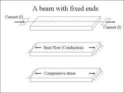
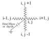
Figure
1. A beam with fixed ends with
Electro-Thermal heat-actuation.
The 3
domains are (1) Electrical, (2) Heat Flow and (3) mechanical
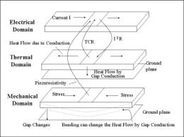
Figure 2. Various
cross-interactions between the 3 domains
4.
PSPICE IMPLEMENTATION OF THE DOMAINS
The simulation of the
electrical and thermal equivalent circuits of the MEMS structure are done
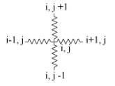
simultaneously using circuit analysis program PSPICE. Each mesh element shares
the electrical, heat and mechanical parameters. In PSPICE circuit simulations each of the domains is implemented by a
4-star connected at every mesh point. The Laplacian operator
![]()
is implemented by 4-star
connected resistors
The generalized equation
containing the 2nd order and 1st order derivatives; a
term in y and a forcing function i(t) is given below
![]()
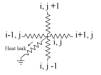
The 4-star connected
equivqlent circuit that implements the above equation is given below. The time
derivative “dy/dt” is implemented by a capacitor connected to the node point (i,j) and
ground. The capacitor is also used as analog of “heat mass”. A resistor
connected between node point (i,j) and ground implements a heat loss by
gap-conduction. A current source (as a function of time) implements a “heat
source” connected to the node point. Thus a genralised implementation of a 2nd
order Laplacian or Poisson’s equation is shown below in figure 3.
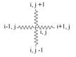
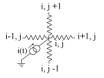
(a) Laplacian operator (b) 1st Derivative term (c) Input function (d) term prpoprtional to y
Figure 3. Implementation of
different terms in a Laplace or Poisson equation
4. PSPICE SIMULATION OF HEATUATOR
The
heatuator, used for demonstrating use of PSPICE for Electro-Thermal simulations,
is shown in figure 4 - narrow and wide arms have widths of 10 um and 30 um
respectively while the length and thickness are same for both arms – 2 mm and
100 mm.
The mesh of 10 mm
x 10 mm
is constructed and each mesh is constructed out of the equivalent circuit
consisting of 4-star connected resistors and a capacitance to ground as given
in section 3 above. The electrical mesh and heat-flow mesh interact with each
other and give us both electrical and heat quantities – we are interested in
temperature profile of the heatuator for a 10 mA current through the device.
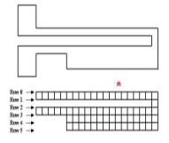
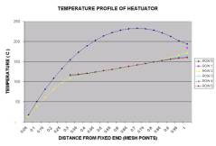
Figure 4. A polysilicon
Electro-Thermal heat-actuator having arms with different widths.The star *
shows the mesh location that has the maximum temperature. .
The simulation using PSPICE for the temperature profile is given figure 5. The transient simulation is straight forward in PSPICE and is obtained by giving a pulse of 10 mA with a pulse width of 200 micro-seconds (figure 6). The thermal mass acts as a ‘capacitance’ and gives a time constant of 40 mS for the narrow arm and 100 m-sec for the wide arm.
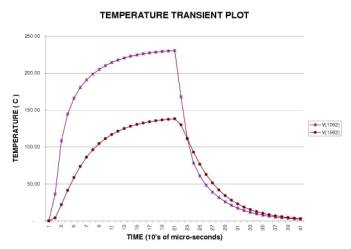
Figure
6. PSPICE transient simulation of the
heatuator at its hottest point in the narrow arm (top curve) and a point below
that in the wider arm (lower curve). Time constants for the two regions are ~40
mSec and ~100 mSec respectively
5.
CONCLUSIONS
Electrical and Thermal simulation for a
heatuator structure have been performed using PSPICE circuit simulator. Once
the mesh sub-circuits are defined then a variety of simulation options of
PSPICE become available. This paper has used only DC and Transient simulation
and estimated the thermal time constant of the heatuator MEMS structure. The
sub-circuit definitions include non-linearities and cross coupling between
various domains. Thus, a set of meshes will act in a manner similar to that a
multi-physics element acts in ANSYS.