Fringing Fields: Fringing is a phenomenon observed at the ends of a dipole antenna, where the electric and magnetic fields extend beyond the antenna's physical length.
Due to the Fringing Fields at the open ends of the dipole, the effective length of the dipole is more than the physical length.
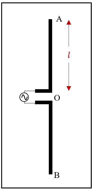
The antenna acts as an open circuited transmission line at the end points A and B.
Let us consider the portion \(l = OA:\)
According to the formula, for a lossless transmission line,
$$Z_{IN} = Z_o \left[ \frac{Z_L + jZ_o \tan(\beta l)}{Z_o + jZ_L \tan(\beta l)} \right]$$
$$ ∴Z_{IN} = Z_o \left[ \frac{1 + j(\frac{Z_o}{Z_L}) \tan(\beta l)}{(\frac{Z_o}{Z_L}) + j\tan(\beta l)} \right] $$
For open circuit \((Z_L → ∞)\):
$$ ∴Z_{IN} = \frac{Z_o}{j \tan(\beta l)} = -j Z_o\cot(\beta l)$$
For \(λ/4 < l < λ/2: cot(βl) < 0 \)
Hence, \( Z_{IN} > 0 \rightarrow \) Inductive
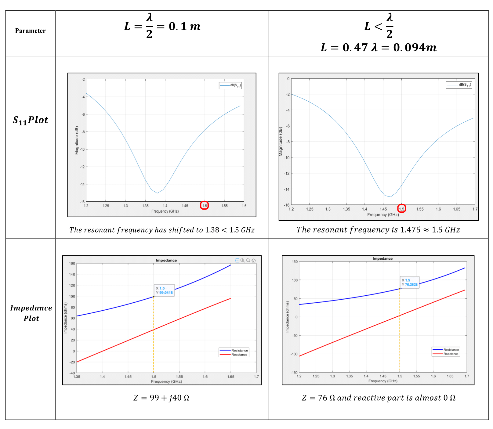
Experimentally, we get a total impedance of approximately \(Z=73+j42.5 Ω\) where the reactive term indicates inductive behaviour.
For the resonance condition, the reactive part should be 0. Hence to get a real impedance the physical length of antenna should be reduced so that the effective length becomes \(λ/2\).
Thus, we have taken total physical length \(L = 0.47λ = 0.094\text{m} (< 0.5λ)\) for a frequency of \(f=1.5\text{ GHz}\)