

Software Used: MATLAB R2023a
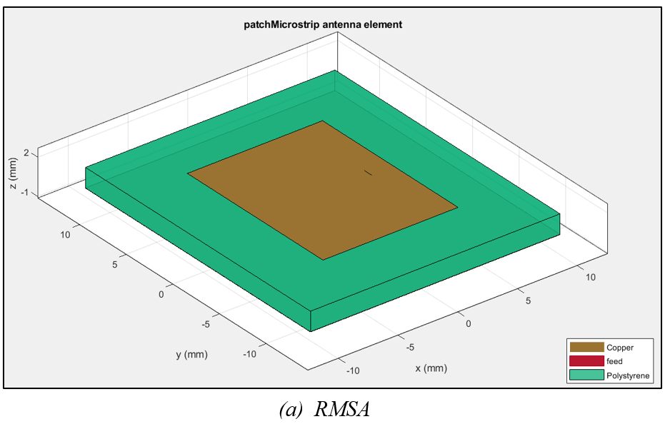
(1) Figure (a) shows a rectangular patch antenna, designed for a resonant frequency, \(f_o=8\text{ GHz}\) with a substrate of dielectric constant \(e_r = 2.32\) and a thickness \(h=0.16 \text{ cm}\)
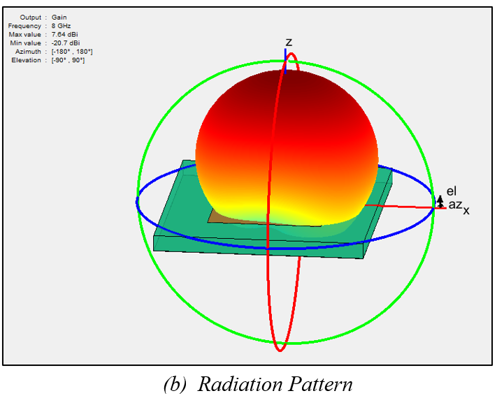
(2) Figure (b) shows the Radiation Pattern. Maximum gain \(=7.64 \text{ dBi}\)
(3) As per the formulae mentioned here, the design results obtained are as follows -
$$ L_{eff} = 12.959 \text{ mm}$$
$$ ΔL = 0.81305 \text{ mm}$$
$$ L = 11.333 \text{ mm}$$
$$ W = 14.553 \text{ mm}$$
$$ e_{eff} = 2.0934$$
$$ L_g = 20.933 \text{ mm}$$
$$ W_g = 24.153 \text{ mm}$$
$$ \text{**Feed point} (x) = 3.78 \text{ mm}$$
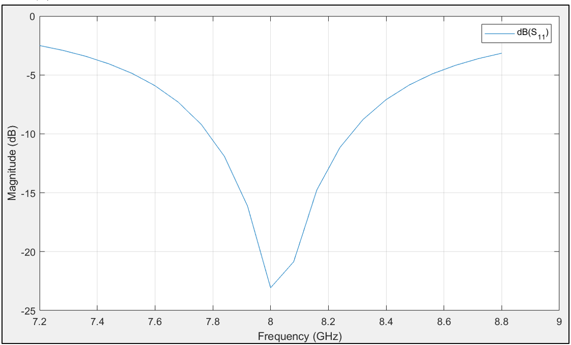
(4) Following is the S11 Plot -

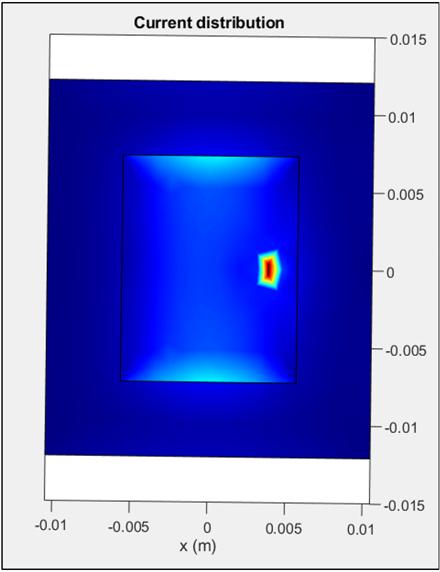
(5) Following is the current distribution -
According to the image, it can be observed that along the length \(L\), the current is maximum at the center and minimum at the edges.
The same distribution extends all along the width \(W\).
Whereas the voltage has its peak at the edges and is zero in the center.
