Software Used: Ansys Electronics Desktop Student (HFSS)
(1) Figure (a) shows the variation of Electric Field vectors.
(2) Figure (b) shows the variation of Magnetic Field vectors.
(3) Figure (c) shows Current vectors. It can be verified that the current is maximum at the center of the length and minimum at the two edges (widths) and this variation continues along the width.
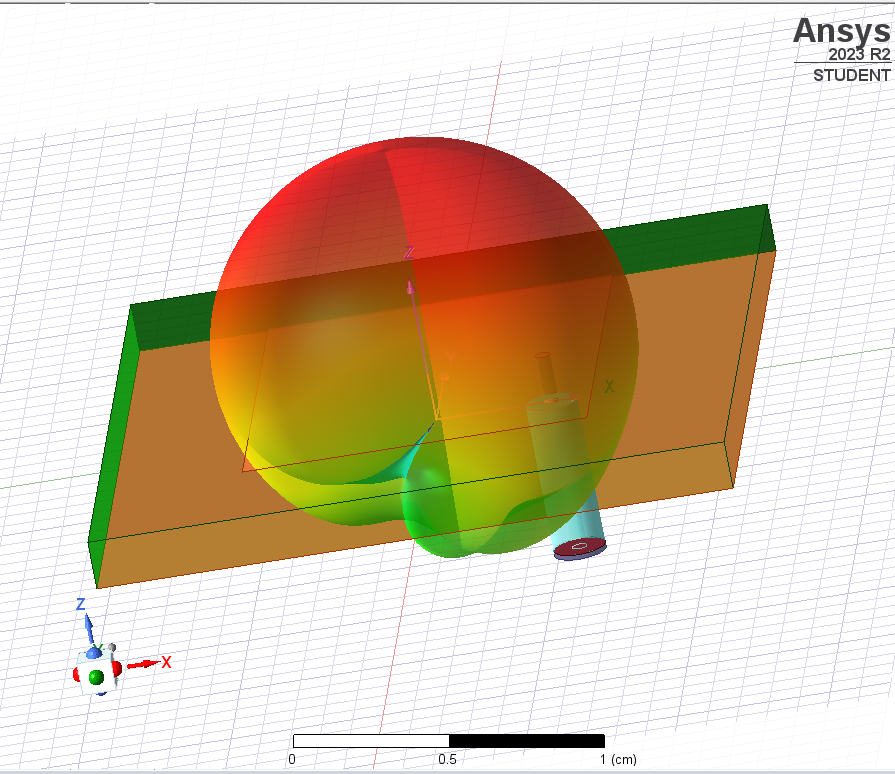
(4) Figure (d) shows the Radiation Pattern.