AC-DC Converters
Basics
As far as the experiment is concerned AC-DC convertors are used for
- providing field excitation for alternators
- controlling the speed of the DC motor which acts as prime mover
Power Electronic converters use semiconductor devices which are operated in " ON " and "OFF" states. In ON state, the voltage across the device is negligible, while in an OFF state, current flowing through it is negligible. The state of a device is decided by the external circuit conditions and a (a low power) signal which is provided at the GATE terminal of the device. Diodes do not have a GATE terminal and their state is wholly determined by the external circuit (forward or reverse bias). Currently, most power electronic converters used in power system applications use a device known as a thyristor. Thyristors are available at ratings in excess of 10 kV, 8000 A. Many thyristors can be connected in series to yield larger equivalent voltage ratings which are required for power system applications.
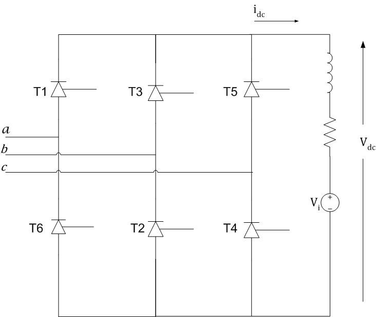
Most AC-DC converters use line commutated thyristor bridges. These converters use the AC voltages to provide the required forward voltages which are essential for thyristor turn on. A "six pulse" thyristor bridge can implement an AC-DC converter, and is shown in the figure below. It is assumed here that the AC side voltages are balanced and the phase sequence is a-b-c.
Operation
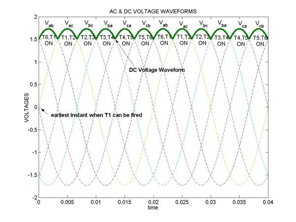
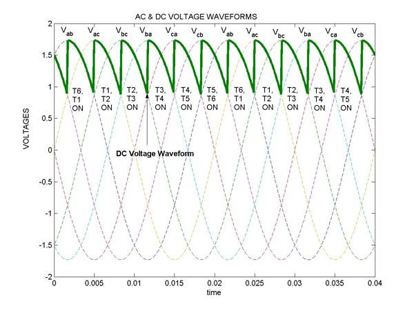
The basic idea is to construct the DC side voltage waveform by parts of the three phase AC voltages. For example, when thyristors 1 and 2 are ON, the voltage across the DC side is Vac.
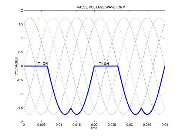
Of course, one cannot switch on the thyristors randomly: they need to be forward biased in order that they may be switched ON. Moreover if thyristors are fired in a particular sequence, indicated by the numbers 1-6 on the side of the devices (see the figure), and fired at the instant when they get forward biased, then the resulting steady state waveforms are as shown. These waveforms are similar to those of a diode bridge. Note that a switching takes place every 60o in a cycle.
It is assumed here that the dc side inductance value is large, dc resistance is small , and the DC source voltage Vi is smaller than the average of Vdc(t) over a cycle. This can ensure that the current on the dc side does not touch zero and is practically a constant. In fact, for most applications, the inductance value is large enough to ensure a smooth dc side current.
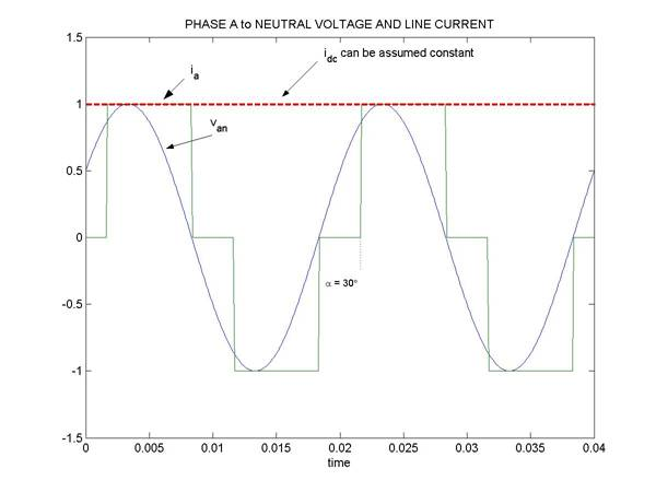
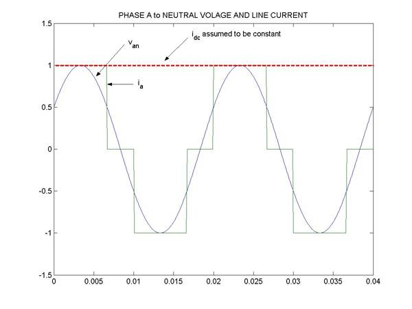
It is clear that if the firing sequence is maintained as given above, then each device conducts for 120o in a cycle. The fundamental component of the current on the AC side is in phase with the corresponding phase to neutral voltage.
Note: The waveforms shown are representative of the steady state and not the transient behaviour. When a bridge is started, current will gradually build up. For current to start flowing on the DC side, it is important that two thyristors be on (one each in the top and bottom half of the bridge). Therefore, while the thyristors are fired in sequence T1 to T6 in a cycle, the gate signals are maintained for more than 60o so that a couple of thyristors will be in a position to turn on when a bridge is started. Also during starting, Vi should aid buildup of current.
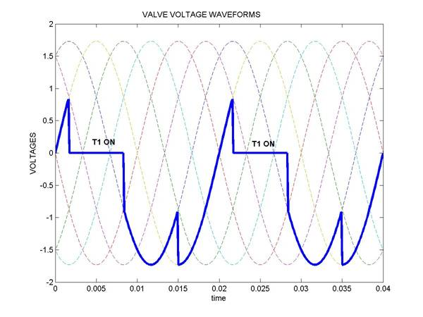
It is assumed here that as soon as a thyristor is switched on in the top or bottom half of the bridge (e.g. T1), then the previously conducting thyristor in that half (e.g. T6) switches off immediately. In actual practice, the current in the "outgoing" thyristor T6 dies down gradually due to source inductances (not shown here). This is known as commutation delay.
AC-DC converter control
Now suppose the thyristors are not fired as soon as they are forward biased, but fired after some delay.
Let us define delay angle for thyristor T1 as the angular delay from the point at which Vac becomes greater than zero. Similarly the delay angle for the thyristors T2, T3..T6 is defined by the angular delay from the points at which Vbc, Vba, ... Vab become greater than zero respectively.
If all the thyristors are fired at a delay angle  of zero, then we get the waveforms as shown in the previous section. However, if we fire all thyristors at a delay angle of 30o we get the waveform shown below.