Basic Theory of Electromagnetic Power Conversion
Generic structure of electrical machines
Electrical machines convert electrical energy to mechanical energy and vice-versa.
In the motoring mode, the electrical power is converted
into mechanical power. All the machines have a stationary part called as
stator and a rotating part, called rotor. They are separated by an
air gap thus allowing the rotor to rotate freely on shaft, supported
by bearings. The stator is firmly fixed to a foundation to prevent
it from turning. Both stator and rotor are made up of high permeability
ferromagnetic material and the length of the air gap is
kept as small as possible (of the order
of 0.5-1 mm) so that the ampere turns required to
establish the
flux crossing the airgap are very small.
You should also note that to reduce eddy-current losses, the stator and
rotor are consist of laminations of silicon steel (see photo below). These laminations are
insulated from each other by a layer of thin varnish.
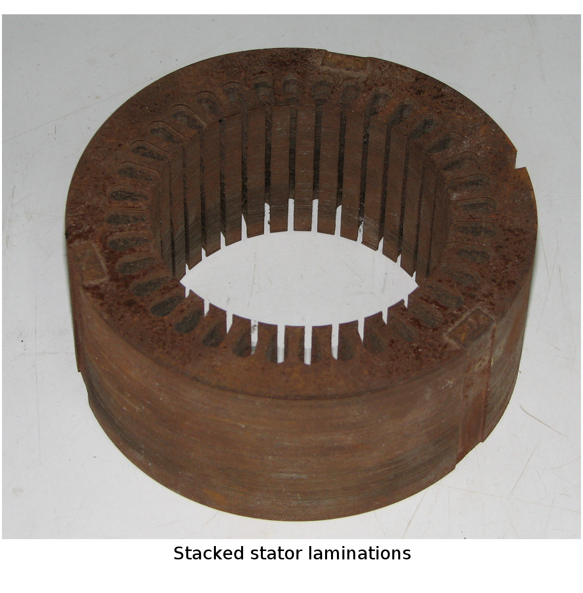
These laminations
are stacked together, perpendicular to the shaft axis. Slots may be cut
into these laminations to place the conductors.
Salient and non-salient pole machines
If rotor and stator
are perfectly cylindrical, the air gap is uniform and the magnetic reluctance
(similar to the resistance in electric circuits) in the path of flux lines
crossing the air gap is uniform.
 Machines with such structures are called
non-salient pole machines as shown in figure above. Sometimes, the machines are purposely
designed to have saliency so that the magnetic reluctance is unequal along various
paths as shown in figure. Such saliency results in
what is called, the 'reluctance torque', which may be the primary or a significant means of producing torque.
Machines with such structures are called
non-salient pole machines as shown in figure above. Sometimes, the machines are purposely
designed to have saliency so that the magnetic reluctance is unequal along various
paths as shown in figure. Such saliency results in
what is called, the 'reluctance torque', which may be the primary or a significant means of producing torque.
Principles of operation
There are two basic principles that govern the operation of electric machines :
- A current carrying conductor placed in a magnetic field experiences a force
- A voltage is induced in a conductor moving in a magnetic field
Now, consider two bar magnets pivoted at their center on the same shaft. There
will be a torque, proportional to the angular displacement of the bar
magnets, which will act to align them. This physical picture is useful in
analysing the torque production in machines.
Currents in the machine windings create magnetic flux in the air gap
between stator and rotor. This condition corresponds to the appearance of
magnetic poles on both the stator and the rotor, centered on their respective
magnetic axes as shown in figure. 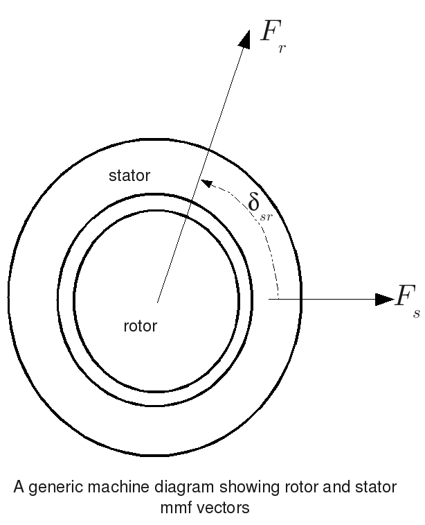
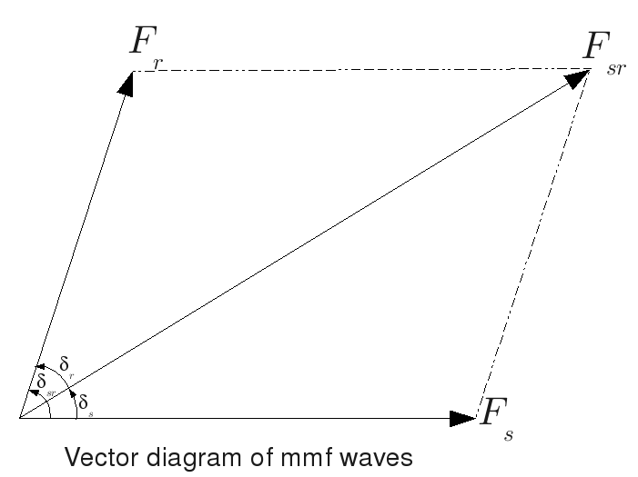 Torque is produced by the tendency of these
two magnetic fields to align. The resulting torque
is proportional to the product of the amplitudes of the stator mmf
Torque is produced by the tendency of these
two magnetic fields to align. The resulting torque
is proportional to the product of the amplitudes of the stator mmf  and rotor mmf
  , and sine of the angle
 measured from the axis of stator mmf wave to that of the
rotor. Therefore the generalized expression for torque is given by
measured from the axis of stator mmf wave to that of the
rotor. Therefore the generalized expression for torque is given by
 Do note that all the flux does not link both stator and rotor.
It is the mutual flux (flux which links both stator and rotor) which is responsible for output power. The flux, which does not link both stator and rotor is called as leakage flux. Leakage flux does affect the machine performance.
From the diagram it can be seen that the above torque equation can be written as
Do note that all the flux does not link both stator and rotor.
It is the mutual flux (flux which links both stator and rotor) which is responsible for output power. The flux, which does not link both stator and rotor is called as leakage flux. Leakage flux does affect the machine performance.
From the diagram it can be seen that the above torque equation can be written as
 A steady torque is developed only when both the fields are stationary
with respect to each other. This is the essential condition for the machine
to develop steady torque.
A steady torque is developed only when both the fields are stationary
with respect to each other. This is the essential condition for the machine
to develop steady torque.