Basics of DC machines
DC machines are the first rotating electrical machines discovered. After the advent of AC machines use of DC machines were used only for specific applications. DC machines are used as prime movers of synchronos generators at power stations. They are also an important part of the excitation systems employed at generating stations.
Structure
The stator of a DC machine has projected poles (salient poles) and a
coil is wound on these poles as shown in figure. When excited by DC current,
air-gap flux distribution created by this winding is symmetric about the
center line of the field poles. The field produced by the stator current
is stationary with respect to stator. This axis is called the field axis or
direct (d) axis. The rotor of DC machine has slots which contain a winding. This winding
handles electric power for conversion to (or from) mechanical power
at the shaft. In addition, there is a commutator affixed to the rotor.
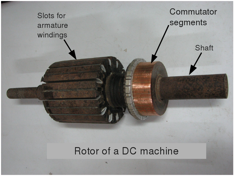
The commutator on its outer surface contains copper segments, which are
electrically insulated from each other by means of mica. The coils of the
rotor (armature) winding are connected to these commutator segments.
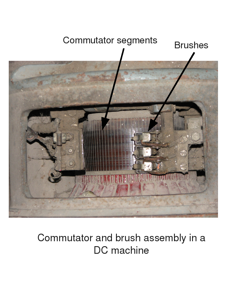
A set of stationary carbon brushes are placed on the rotating commutator. These brushes are fitted to the stator. It should be noted that the wear due to mechanical contact between the commutator and the brushes requires regular maintenance, which is the main drawback of these machines.
Principle of Operation of DC Machines
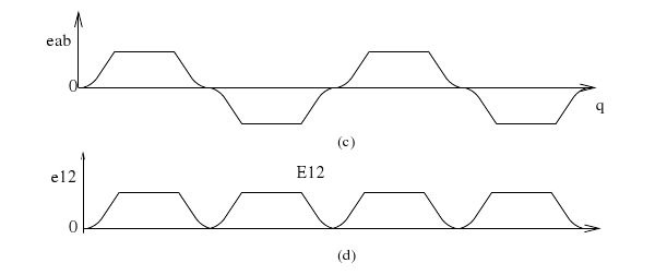
Consider a two pole DC machine as shown in figure below. The voltage induced in the rotor coil rotating
in a uniform field established by the stator is alternating. The air gap flux distribution and the voltage
induced in the coil are shown in figures (b) and (c).
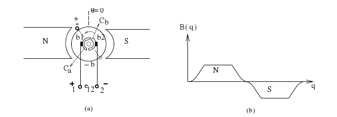
Consider a coil a-b is placed on diametrically opposite slots of the rotor shown in figure (a) above. The two ends of this coil are two commutator segments which
are rotating. Coil a is connected to segment Ca and coil b to segment Cb . Let B1 and B2 be the two
carbon brushes. These brushes are stationary. For counterclockwise motion of the rotor the terminal
under north pole is positive with respect to the terminal under south pole. Therefore, B1 is always
connected to positive end of the coil and B2 to the negative end of the coil. Thus even though the
voltage induced in the coil is alternating, the voltage at the brush terminals is unidirectional as shown
in figure.
The rectified voltage across the brushes has a large ripple (magnitude is not constant, it is
varying) as shown in figure (d) above. In a actual machine a large number of turns are placed in several slots around the periphery
of the rotor. By connecting these in series through the commutator segments a reasonably constant DC
voltage is obtained. The magnitude of the voltage induced in the armature is proportional to  where
where  is the airgap flux and
  is the speed of rotation.
Now let's look at the role of commutator.
Current reversal in a turn by commutator and brushes is shown in the figure below. The end 'a'
touches the brush B1 . The current flows from a to b. As this coil rotates, at a particular position it
gets short circuited (refer next figure).
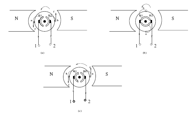
The angle between the d-axis and this position is 90o . As the coil
rotates from this position, end 'a' now touches brush B2 . The current now flows from 'b' to 'a' as shown
in figure. Hence, the commutator and brushes rectify the alternating voltage induced in
the armature to DC. This combination is also known as mechanical rectifier. Though the
current flowing in the armature conductors is AC, the current flowing in/out of carbon
brushes is DC. The change over from positive to negative value takes place at a particular
axis. The angle between this axis and the d-axis is always 90o . Therefore, this axis is
known as q-axis or the quadrature axis. Since, the armature mmf (Fa) is along this axis,
the angle  is always 90o .
Governing Equations
It is often convenient to discuss a DC machine in terms of its
equivalent circuit shown in figure. which shows the conversion
between electrical and mechanical power or vice-versa. Field produced
by the stator is represented by current  flowing in the coil.
At steady state the equation relating this current and applied voltage
to the field coil is
flowing in the coil.
At steady state the equation relating this current and applied voltage
to the field coil is 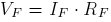 , where
  is resistance
of the field coil.
is resistance
of the field coil.
If is the air gap flux,
and is the speed of rotation, the expression for the
voltage induced in the armature is given by  , where
  is a constant. Let
  be the armature resistance
and
be the armature resistance
and  be the armature current.
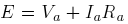
Equations for motor
Here the current is assumed to flow into the positive carbon
brush (see figure (b)). The relationship
between the steady state voltage induced in the armature  and the
armature terminal voltage
and the
armature terminal voltage  is
is
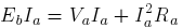
 Multiplying throughout by , we get
 The term on the LHS in above equation is the power input to the armature,
first term on RHS is the power lost as heat in the armature resistance and last
term is power developed in the armature. This developed power should be
equal to the mechanical output power
The term on the LHS in above equation is the power input to the armature,
first term on RHS is the power lost as heat in the armature resistance and last
term is power developed in the armature. This developed power should be
equal to the mechanical output power  if friction is neglected.
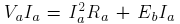
Equations for generator
In this case is leaving the positive brush as shown
(see figure (c)). The relationship between the steady state voltage induced in the armature and the
armature terminal voltage is
 The power balance equation would be then,
 The following points may be noted from these equations
