Synchronous machines are extensively employed as generators in three phase AC power systems. Hence this article is focussed more on synchronous generator. As it has been told in basics of electromagnetic power conversion, synchronous generator or alternator as it is called uses the Faraday's law of electromagnetic induction to develop an emf across the windings. Three phase power is used due to its advantage of constant instantaneous power. Hence three phase generators are most common.
There must be a field winding and an armature in which the emf will be induced. Typical construction has field winding on the rotor and armature winding on the stator. Note that this is opposite to that of a DC machine. High speed turbo-generators have non-salient or cylindrical rotor construction. Ususally they are driven by steam turbines. Whereas the alternators driven by hydro-turbines have salient pole alternators. Field winding is excited by a DC voltage and has same number of poles as that on stator. Each phase of armature winding on stator is displaced in space by 120o electrical from other (for three phase construction which is the most commonly deployed). The analysis assumes that the flux produced by the field winding is sinusoidally distributed in the air gap. When the field rotates at constant speed, flux which links the stationary armature winding varies sinsoidally with time. This produces the three phase emfs in the armature which are displaced in time by 120o electrical from each other.
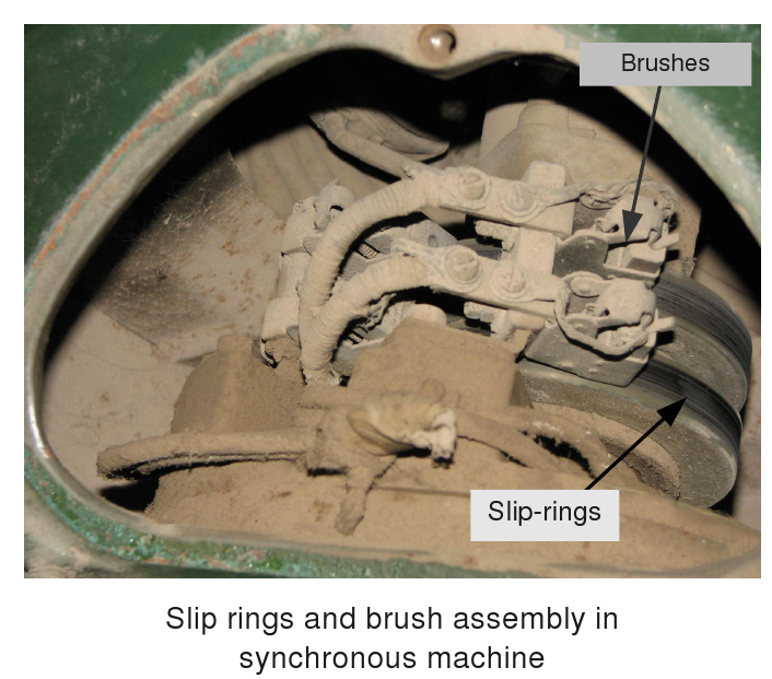
The rotor has windings which carry DC current. These field windings are excited via slip-ring and brush assembly. Note that this is not the same as the commutator and brush assembly in DC machine. The slip-rings have no "segments"; they are two full rings connected to the DC supply. This can be seen from photo given below.
The voltage induced in the armature winding undergoes a complete cycle when one pole pair sweeps by. Thus in one mechanical revolution it undergoes  cycles, where
  is number of poles. Hence if
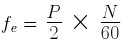
  is the speed of prime mover in rpm then the frequency of induced voltages is
 is the flux linkage per pole per phase then
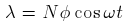
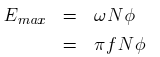
 is the flux per pole linking the winding. Hence emf induced in each phase winding having turns is
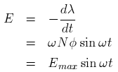
 is mechanical frequency of rotation of the rotor.
The induced emf in each of the phases has same magnitude but they are displaced in phase from each other by 120o.
is mechanical frequency of rotation of the rotor.
The induced emf in each of the phases has same magnitude but they are displaced in phase from each other by 120o.
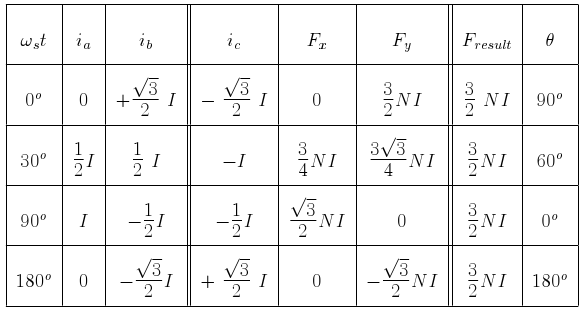
turns each, displaced in space by 120o degrees and connected to a balanced 3 phase system as shown in figure. The coils are depicted to be single turn coils. Further this diagram shows only two pole machine. This is just to simplify the analysis. Similar analysis can be done for more complicated cases. 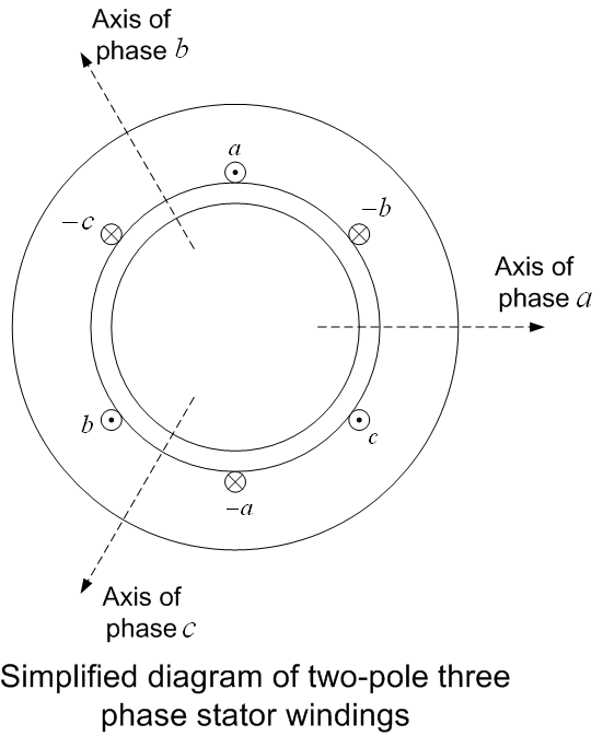
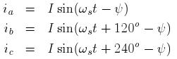
 . Then instantenous armature currents are