Synchronous machine : Equivalent Circuit
(The analysis given below pertains to cylindrical rotor machines.)
We shall now develop the equivalent circuit of synchronous machine. This shall be developed by means of following diagrams. Note that these are combined phasor vector diagrams. Let  be the field mmf produced. This generates the induced emf
  in the armature windings of a phase. If we connect a load then a current flows which lags this open circuit generated voltage by
  as shown in figure. This current will produce a field of
  which will be in phase with current. Note here that , the no load generated voltage is a time phasor whereas is space vector.
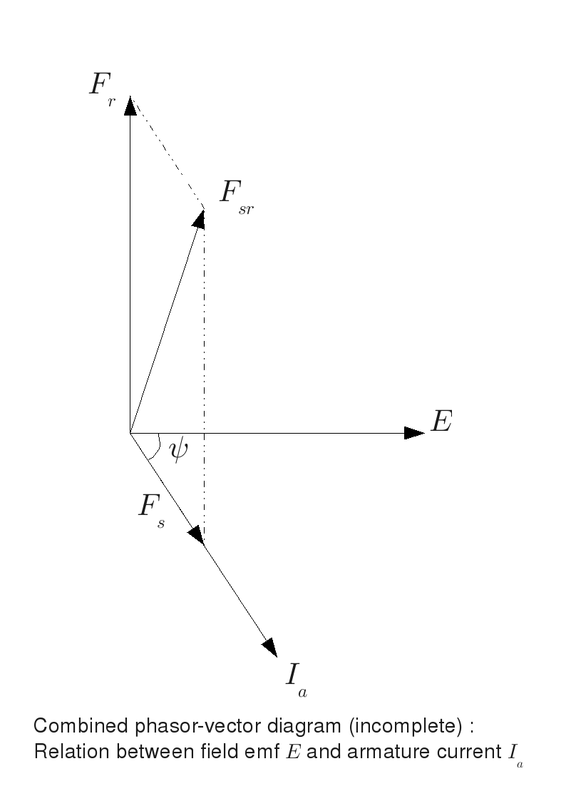
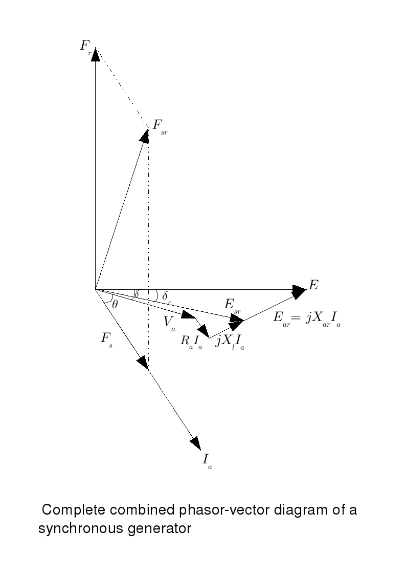
Now this field interacts with the field produced by the rotor to give the resultant field  as shown in the diagram. It is interesting to see the effect of this field on the coils which produce this field. As the field is time varying, it induces the emf called as armature reaction emf (
 ). From Lenz's law, this will try to oppose
  . Therefore, its polarity, at any given instant, will be opposite to that of . Thus will lead by 90o. Hence it can be shown by an equivalent reactance
  . Note that (actual) on-load generated emf differes from the no-load value by , or equivalently by
  .
.
The terminal voltage  differes from this due to the resistive drop and the leakage inductance drop. These two are represented by
  and
and  . (Leakage here refers to the flux which is wasted i.e. it does not link the stator coils and does not take part in energy conversion. Hence some fraction of the total current is not actually utilised for energy conversion. This effect is taken care of by considering leakage inductance.)
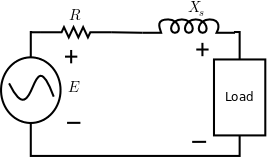
Ususally the leakage reactance is considered together with the armature reactance the addition is termed as synchronous reactance . This leads to a simple equivalent circuit of the synchronous machine as shown in figure.