(You should know the basic theory of DC machines before reading this)
It is essential to vary the speed of the DC motor as the load demands. In case when the load is alternator (i.e. DC motor is prime mover), as the speed of motor varies so does the output voltage of the alternator. It is necessary to keep the output voltage of the alternator constant inspite of the varying load on the alternator. This is achieved via speed control of prime mover via AVR loop. Speed control of DC machine is a part of AVR loop.
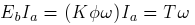
We know that
 in terms of torque and flux, the relationship
between
in terms of torque and flux, the relationship
between  and
and  is given by:
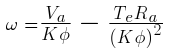
 and airgap flux
  are held constant,
the above equation can be written as:
are held constant,
the above equation can be written as: 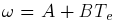
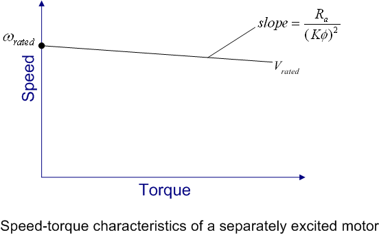 and are held constant, the speed of a separately excited
dc motor will remain almost constant and it is independent of torque
applied to the shaft. Hence in order to vary the speed of over
a wide range, the no-load speed (magnitude of
and are held constant, the speed of a separately excited
dc motor will remain almost constant and it is independent of torque
applied to the shaft. Hence in order to vary the speed of over
a wide range, the no-load speed (magnitude of  ) should be varied. This can
be achieved by the following methods:
) should be varied. This can
be achieved by the following methods:
The schematic diagram for this control technique is shown in figure.
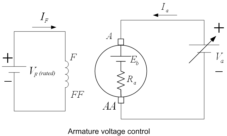 is varied.
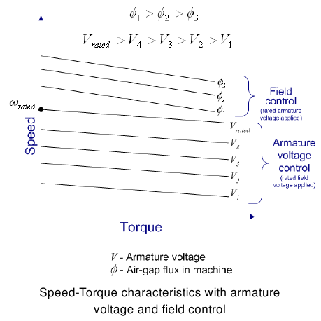
The speed-torque characteristics for this method are shown in figure at the bottom of the page. These
characteristics are drawn for various values of and fixed
value of flux. This method of speed control is used for speed below the
rated value. It is worth noting that since is held constant, the speed of
rotation changes linearly with . Motor
will draw a constant armature current from the source
if it is driving a constant torque load. Under this
working condition, the power (P) drawn by the motor varies linearly with
the speed. This mode of operation is known as constant flux or
constant torque mode
is varied.
The speed-torque characteristics for this method are shown in figure at the bottom of the page. These
characteristics are drawn for various values of and fixed
value of flux. This method of speed control is used for speed below the
rated value. It is worth noting that since is held constant, the speed of
rotation changes linearly with . Motor
will draw a constant armature current from the source
if it is driving a constant torque load. Under this
working condition, the power (P) drawn by the motor varies linearly with
the speed. This mode of operation is known as constant flux or
constant torque mode
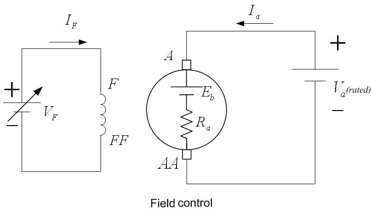 .
The speed torque characteristics for this method are shown in figure at the bottom of the page. This portion of speed cpntrol is called as field weakening zone. These characteristics are drawn for various values of and fixed value of . It should be noted that the reduction in speed with torque is
higher compared to that in the previous method. This method of speed control is used for speed above the
rated value. It is worth noting that this is a inverse non-linear control of motor speed. This method
also changes the value of developed torque for a given armature current.
If the armature current is held constant at the rated value, the input power
and therefore output power remains approximately constant (assuming that
frictional and windage losses remain constant). Hence, this
operating zone is also known as constant hp (horse-power) mode.
Generally the maximum speed of is kept within 150 % of the
rated value.
.
The speed torque characteristics for this method are shown in figure at the bottom of the page. This portion of speed cpntrol is called as field weakening zone. These characteristics are drawn for various values of and fixed value of . It should be noted that the reduction in speed with torque is
higher compared to that in the previous method. This method of speed control is used for speed above the
rated value. It is worth noting that this is a inverse non-linear control of motor speed. This method
also changes the value of developed torque for a given armature current.
If the armature current is held constant at the rated value, the input power
and therefore output power remains approximately constant (assuming that
frictional and windage losses remain constant). Hence, this
operating zone is also known as constant hp (horse-power) mode.
Generally the maximum speed of is kept within 150 % of the
rated value.