
Source/Monitor Unit (SMU) Fundamentals
Introduction
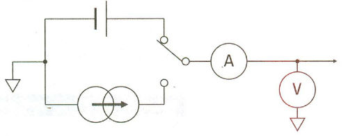
The primary measurement resource for parametric test is the source/monitor unit or SMU. This is also sometimes referred to as source/measurement unit, although acronym ends up the same. The SMU can force voltage or current simultaneously measure voltage and/or current. There are variety of different SMUs. The most common SMU is the medium-power SMU (MPSMU); as the name implies this SMU can supply moderate levels of voltage and current ( ±100V and ±100mA) and current measurement resolution down to 10fA. For precision measurements there is high resolution SMU (HRSMU) and high power SMU (HPSMU) is for situations requiring larger currents and voltages.
SMU Operation modes and Settings
SMUs have three basic modes of operation: voltage source, current source and common. In common mode the SMU acts as a 0V voltage source, it cannot perform any measurement, and current compliance is automatically set to the SMU's maximum value.
Compliance Settings
SMUs have the ability to specify the compliance setting. The compliance setting is always opposite to that of source setting of the SMU (i.e. current compliance when the SMU is in voltage source mode and voltage compliance when the SMU is in current source). When SMU reaches compliance, it acts as a constant voltage or current source. The compliance feature prevents inadvertent device damage by not allowing the measured quantity to exceed the specified compliance value. In addition, on swept sources it is also possible to specify power compliance. The power compliance prevents the total power output by the SMU from exceeding the specified power compliance value. If both standard and power compliance are specified, then the SMU will never exceed whatever is the lower of these two settings.
Measurement Ranging
Measurement ranging is intimately interrelated with measurement accuracy and resolution. However, before proceeding it is important to understand why SMUs have a range setting in the first place. The SMU circuitry has to switch in and out (using relays) different resistor values in order to handle the maximum expected current or voltage value based upon the initial compliance setting specified by the user. An example of the circuitry is shown below:
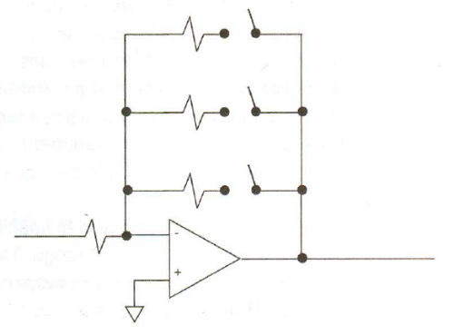
Selecting one or more resistors via these relay switches places the SMU into a given measurement range. Obviously, it takes some time to switch these relays and move from one range to the next. While it would be possible to always have the SMU start at the highest possible measurement range and work its way down to the lowest measurement range that contained the quantity being measured, this would result in extremely slow measurements. By allowing the flexibility as to how a measurement range is selected, the suer gains the ability to trade off measurement speed versus accuracy.
There are typically three types of ranging selectable on an SMU: fixed, limited and auto. The illustration below shows how each of these choices impacts the measurement range used by the SMU:
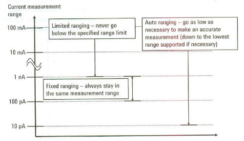
Ranking the measurement ranges in terms of fastest to slowest, the order would be fixed (fastest), limited (next fastest) and auto (slowest). Although fixed measurement ranging yields fastest measurement results, it has a limitation that the SMU will not go into a lower measurement range to improve a measurement accuracy. Also if you attempt to measure a current or voltage in fixed measurement range that exceeds the maximum value of the fixed measurement range you will get a measurement error. Limited ranging and auto ranging are similar in that they both start in the highest measurement range that contains the user specified compliance value, and they both work their way down to find optimal range in which to make the measurement. The difference between the two ranging choices is that ranging will never go below the user-specified range limit. Thus, limited ranging is also useful when you are uncertain of the value of current or voltage that you will be measuring and you do not care about ultra-precise measurement. However, if you absolutely want to have the best measurement accuracy and measurement time is not a concern the auto ranging is the correct choice.
Eliminating measurement noise and signal transients
Integration Time
Inexperienced users sometimes confuse the purposes of measurement ranging and integration time. It is important to understand that the purpose of integrating a measurement over time is to eliminate noise. Increasing the integration time does not have the same effect as using lower range measurement. Before increasing integration time, to improve your measurement result you should first determine if you gave choose the correct measurement range for the level of current or voltage that you are trying to measure. For example, it makes no sense to try and make a femtoamp current current measurement using limited 1nA ranging on an SMU, since the SMU needs to get down into 10pA range in order to make a good femptoamp measurements.
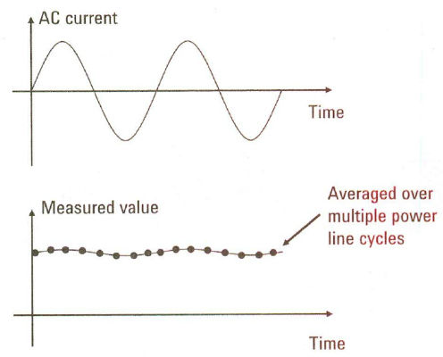
The terminology used for integration time is not uniform across all products. In some cases, the term "Short" is used to refer to any integration time that occurs in a time periods that is less than one power line cycle (PLC); "Medium" is then used to refer to integration over exactly one PLC, and "Long" is used to refer to integration time over multiple PLCs. In other cases, the terms "Auto" and "Manual" are used to refer to integration over one or more PLCs.
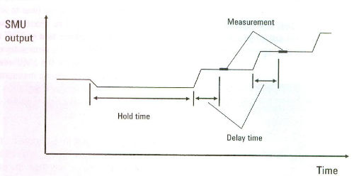
Hold time and delay time
In addition to noise, capacitance on the SMU outputs can cause ringing and other transient phenomena each time the SMU applied a new voltage or current. To insure that the applied voltage or current is stable before making measurement, you can specify both a measurement hold time and a measurement delay time as shown below
The hold time insures that the SMU outputs are stable before the start of a measurement, and the delay time insures that the SMU outputs are stable during a measurement if the value of the SMU output is being changed.
← Back to Resources