
Setup : vega
What can it do?- Room temperature max 3 terminals IV.
- Room temperature 2 terminals CV
- Four terminal measurements can be done by shorting two terminals using switch matrix
 What it cannot do?
- Temperature dependent measurements
- Stress Measurements/ Pulse Measurements
- Keithley 236 SMU - 2 Nos
- Agilent LCR Meter - 1 No.
- Keithley 708 A Switch Matrix - 1 No.
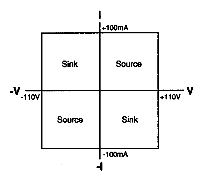
- Through SMU : Max Voltage = 110 Volts
236 Output Specification
Max Current = 100 mA - Through LCR Meter : Max Frequency =20 Hz
Min Frequency =1 MHz
- Two SMUs connected to switch matrix columns 1 (SMU1) & 2 (SMU2)
- GNDU connected to switch matrix column 4
- Manipulator A,B,C & D connected to rows A,B,C & D respectively
- Chuck connected to Row G
- LCR High connected to column 10
- LCR Low connected to column 11
Setup Usage Instructions:
- Login using your charlab domain username and password.
- If you are first time user, copy the codes from E:\Users\codes folder to your network drive. (All the codes are appropriately named)
- Probe your device properly and make a mental note of which manipulators you have used to make contacts.
Code Specific Instructions:
For CV:
- Run the CV_2terminal.exe.
- The code will ask you for the following values
- Frequency (Enter in Hz)
- Start and End values of DC bias sweep (Enter in Volts).
- AC value of voltage (Enter in Volts).
- File name where your data will be stored (for eg: CV_output.dat)
- Integration time (0 for FAST 1 for NORMAL 2 for SHORT).
- Step size
- For Probe connections:(use a,b,c,d,chk for entering the values)
- For example if you are using chuck and probe c for the two terminal CV measurement then
- For high terminal enter : chk
- For low terminal enter : c
- NOTE: DO NOT use chuck as low terminal. you will not get proper CV
- Let the code run. You will get measured values of Capacitance is in picofarads.
- The data sheet will be generated in the same folder and it can be opened with the data plotting software ORIGIN.
For IV
- Run the appropriate code. (IV_2terminal.exe for two terminal IV, IV_3terminal.exe for three terminal measurements)
- The code will ask you for following values
- Start and End values of DC bias sweep. (SMU1 is used to sweep. Its hard coded in the code)
- File name where your data will be stored
- Integration time (0 for FAST 1 for NORMAL 2 for SHORT)
- Step size
- DC bias For SMU2 (If you do not want to force value from other SMU, put it as 0)
- For Probe connections:(use a,b,c,d,chk for entering the values)
- For example if you are using probe A and probe C for the two terminal IV measurement and you want to sweep the voltage on probe A and keep a fixed Bias on probe C then,
- for terminal 1 Enter : a
- for terminal 2 Enter : c
- The data sheet will be generated in the same folder and it can be opened with the data plotting software ORIGIN.
Note: USE NEGATIVE value of step size if stop voltage is negative.
(eg:Start voltage 0 Stop voltage -10 then Step Size =-1 ie a negative value of step size)
NOTE: Users can refer instrument manual kept in cupboard for further assistance.